Things to Consider While Extracting Fluid Domain for CFD Analysis
Posted by: Mehul Patel | Posted on: May 18th, 2015
There has been a tremendous increase in the use of computational fluid dynamics for industrial applications. The ability to quickly simulate internal or external flow behavior makes it possible for engineers to understand the product performance more accurately and implement changes immediately, without going for extensive physical test trials.
However, CFD simulations require certain prerequisites to ensure that the results are valid and are practically useful. Most importantly, the fluid domain utilized for simulation is of prime importance. Unlike traditional CAD model, the CFD geometry is different and only considers the regions or volumes containing fluid. As such it is required to repair or recreate the CFD domain from the existing production CAD model.
Considering an example of turbomachinery, the original CAD model will consist of all the design features of the casing, which in CFD is not required. Thus, it is required to extract the domain from the existing domain by considering only the surfaces that surround the fluid.
Prior to meshing, it is important that the fluid domain is watertight, i.e. the domain is closed properly. This requires creating boundary surfaces for inlet and outlet regions and rectifying errors in the CAD model by removing any gaps between the surfaces, creating any missing surfaces and trimming the surfaces that fall outside the fluid domain.
Also, CFD analysis is known to consume time based on the number of elements used to mesh the fluid domain. As such, it is also necessary to remove geometrical parts that unnecessarily consume more elements. Features such as fillets, chamfers, bolts, nuts and gaskets that would otherwise have negligible effect on the results shall be removed.
However, it is also crucial to understand the purpose of the fillets and champers provided in the design before removing them. In many cases, these features are used to avoid flow separation and its removal from the geometry can cause discrepancy in results.
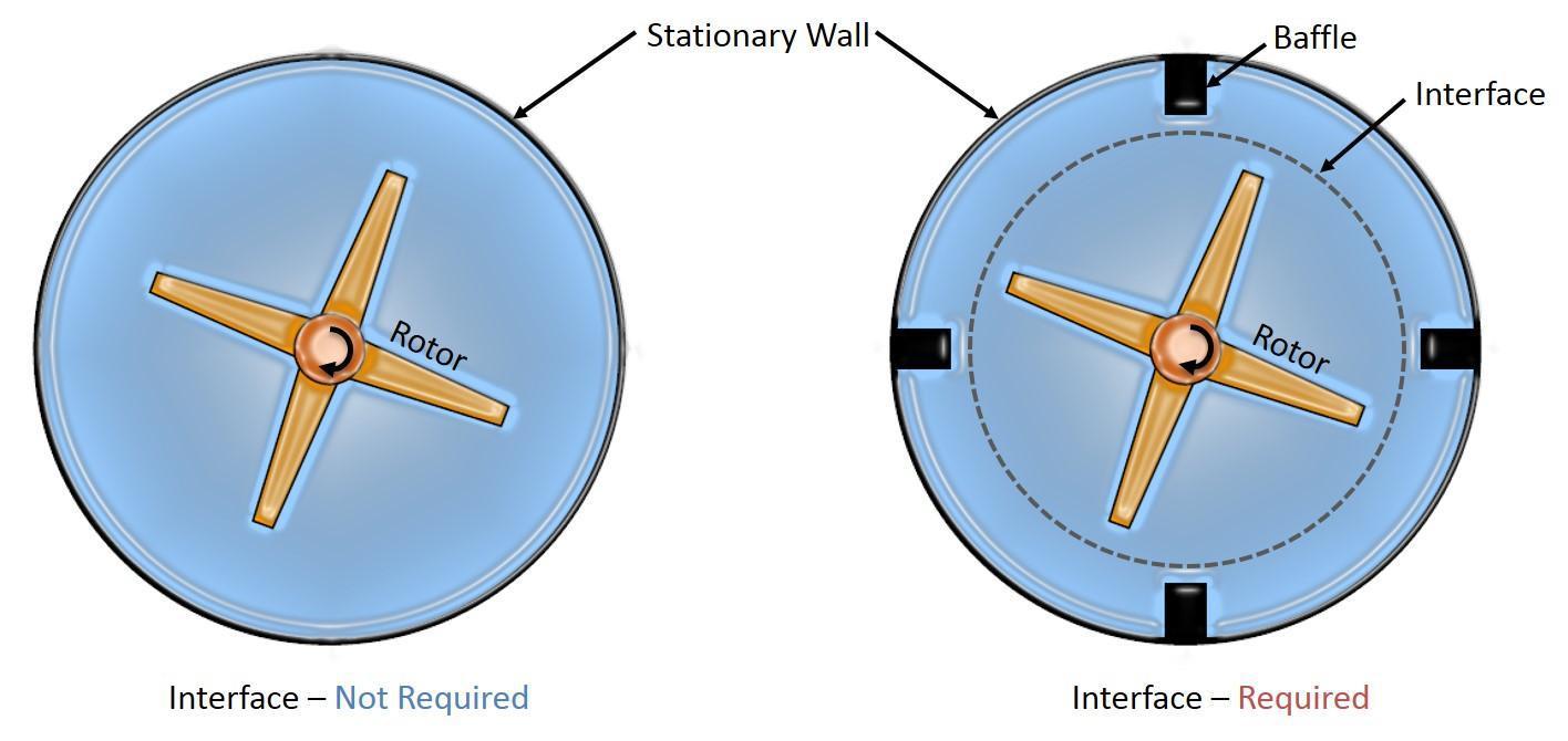
There is also a need to introduce interface in cases of domains containing rotating devices. This is most commonly found in turbomachinery, which consists of rotor in the center and stator around the periphery. Systems like there require dividing the domain into multiple zones, i.e. stationary and moving and both are solved separately, with an imaginary interface that separates these two zones.
In case, where there is only a single rotor, there is no need of any interface, and the domain can be solved using single reference frame approach (SRF). This approach solves fluid flow equations with a moving reference frame, making the solution steady with respect to the frame

About Author: Mehul Patel specializes in handling CFD projects for Automobile, Aerospace, Oil and Gas and building HVAC sectors. He works as a CFD consultant with Hi-Tech CFD for the past 5 years and has successfully executed numerous CFD projects of high complexities. He is an expert in turbo-machinery, gas dynamics, Combustion, Fluid Dynamics, multiphase flow analysis, computational fluid dynamics etc.