Controlling Pressure Drop in Industrial Valves Using CFD
Posted by: Mehul Patel | Posted on: January 15th, 2015
Controlling fluid flow through valves is a common phenomenon in industries using fluid streams for processing purposes. The use of valves and tube fittings however increases the chances of pressure drop in fluidic systems, which is undesirable especially in cases where high pressurized fluid flow is desired at the outlet. It is important therefore to evaluate these flow control devices and identify parameters that affect pressure drop.
Utilizing experimental tests in these cases only reveal inlet and outlet conditions and it is quite complex to determine the process occurring in between. CFD is a cost-effective method to perform pressure-drop studies for valves and can be used as a tool to optimize the fluid systems faster.
A typical CFD simulation requires setting up the problem first by developing a computational domain, which is the actual volume that will be occupied by the valve. The set of fluid flow parameters are also required, which includes the fluid flow velocity, pressure, density and temperature. Additionally, the most important step that will ascertain the accuracy of the CFD results is meshing. The process of meshing requires understanding the fluid domain comprehensively. Usually, a coarse mesh will not be sufficient to capture the flow physics more accurately; the use of fine mesh is indeed required.
Since pressure drop is also dependent on valve opening and closing, it is essential to apply dynamic mesh to regions that open and close to control the fluid flow. Especially, for critical regions of valves, the mesh must be refined so that the effect of turbulence can be simulated more accurately.
Pressure drop in valves usually occur due to flow resistance regions and the subsequent formation of local turbulence zones. As such, the simulation also requires defining proper turbulence models. Two equation models such as k-epsilon or k-omega are capable enough to capture the turbulence effectively.
Fluid flow governing equations are also required to be defined and appropriate solver must be selected. Since valve being a small component, RANS simulation method is appropriate and does not consume much of the computational power.
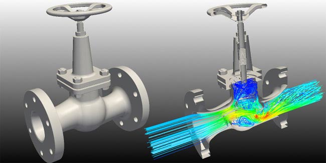
The effect of pressure drop can be visualized using post-processing tools that provide insights about the regions that decrease the fluid pressure. Once identified, several parameters can be altered such as valve geometry, fluid flow conditions or pressure generation equipments. Identifying pressure drop situations prior to actual physical application helps in eliminating design flaws early and save huge amount of time.
Coupling the CFD data with FEA also helps in determining the structural strength of the valves exposed to high temperature and pressure of the fluid using fluid-solid interaction simulation technique. The fluid systems as such can be comprehensively evaluated more easily and rapidly, which can ultimately help manufacturers in improving the overall plant efficiency and cost savings.
Image Credit: http://www.simscale.de/_en/index.php?page=stories/globe-valve

About Author: Mehul Patel specializes in handling CFD projects for Automobile, Aerospace, Oil and Gas and building HVAC sectors. He works as a CFD consultant with Hi-Tech CFD for the past 5 years and has successfully executed numerous CFD projects of high complexities. He is an expert in turbo-machinery, gas dynamics, Combustion, Fluid Dynamics, multiphase flow analysis, computational fluid dynamics etc.