Using Multiple Reference Frame Model for Turbomachinery Analysis
Posted by: Mehul Patel | Posted on: November 24th, 2014
Turbomachinery is a single term given to the devices involving extracting or adding energy to the moving fluid. Its example could be a turbine using kinetic energy of the fluid to rotate the blades and convert the energy into mechanical work; or a compressor, which uses the kinetic energy of the moving blades to compress the fluid and increase its pressure. These rotating machines or turbomachinery are often being evaluated for performance using CFD techniques, as analytical solution is often difficult and time-consuming. CFD simulations can be extremely useful in predicting the performance, visualize internal flow distribution and investigating existing design.
Two common approaches used for turbomachinery simulations are: (1) Multiple Reference Frame Model (MRF) and (2) Single Reference Model (SRF), out of which, MRF is the most widely used model because of its simplicity. Known also as the “frozen rotor approach” MRF assumes that the volume being assigned to study the fluid flow behavior rotates at a constant speed of rotation and the non-wall boundaries are surfaces of revolution. It is a stead-state approximation in which cell zones can be assigned different rotational or translational speeds. It is similar to running a rotational simulation while freezing the position of the rotor at every instant and observing the results.
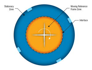
Considering an example of a mixing tank with a single impeller, a moving reference frame can be defined encompassing the impeller as well as the surrounding flow. The flow outside the impeller region is defined as stationary frame. The interface between these two reference frames is assumed to have steady-state flow conditions, i.e. the interface serves as a surface of revolution, distinguishing the two reference frames.
For the stationary frame, mass, momentum, energy and other equations are solved, while fluid acceleration in moving frame is defined using relative velocity of rotating and stationary frame. The acceleration terms in the moving frame is used to modify the convection and source terms in the momentum equations.
Contrary to MRF approach, the single reference model assumes that the rotor is rotating and the mesh is also rotating along with it at the same rotational speed of the rotor blades. The interface between moving and stationary domain is sliding surface. While this approach is capable to capture the details more effectively, it consumes large amount of computational power, making it costly.
Ideally, for rotating machines or turbomachinery analysis, MRF approach should be considered as a first hand analysis to simulate rotating effects using steady-state simulation. Based on the complexity of the project, further simulations using SRF approach can be utilized for better insights on fluid flow.

About Author: Mehul Patel specializes in handling CFD projects for Automobile, Aerospace, Oil and Gas and building HVAC sectors. He works as a CFD consultant with Hi-Tech CFD for the past 5 years and has successfully executed numerous CFD projects of high complexities. He is an expert in turbo-machinery, gas dynamics, Combustion, Fluid Dynamics, multiphase flow analysis, computational fluid dynamics etc.